Picture Content Information
▪ Device:
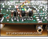
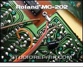
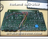
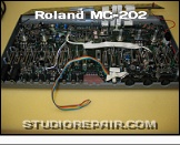
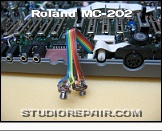
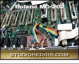
Roland MC-202
▪ Topic:
CV/Gate Modification
▪ Abstract:
Now there's free space for the two new jacks.
▪ Creator:
Image by
Nikolaus Riehm
▪ Website:
studiorepair.com
▪ Editor:
Nikolaus Riehm
STUDIO REPAIR
»
Roland
»
MC-202
»
CV/Gate Mod
»
CV/Gate Modification
[Image 3 of 12]
::
Jump To
+ Kenton Socket Kit
- CV/Gate Mod
Roland MC-202 • CV/Gate Modification
Now there's free space for the two new jacks.
Roland MC-202 - CV/Gate Modification - Image by
Nikolaus Riehm
©
STUDIO REPAIR NIKOLAUS RIEHM
2006 - 2020