Picture Content Information
▪ Device:
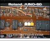
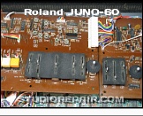
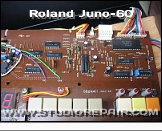
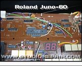
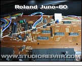
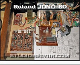
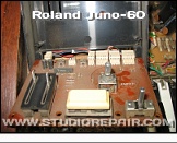
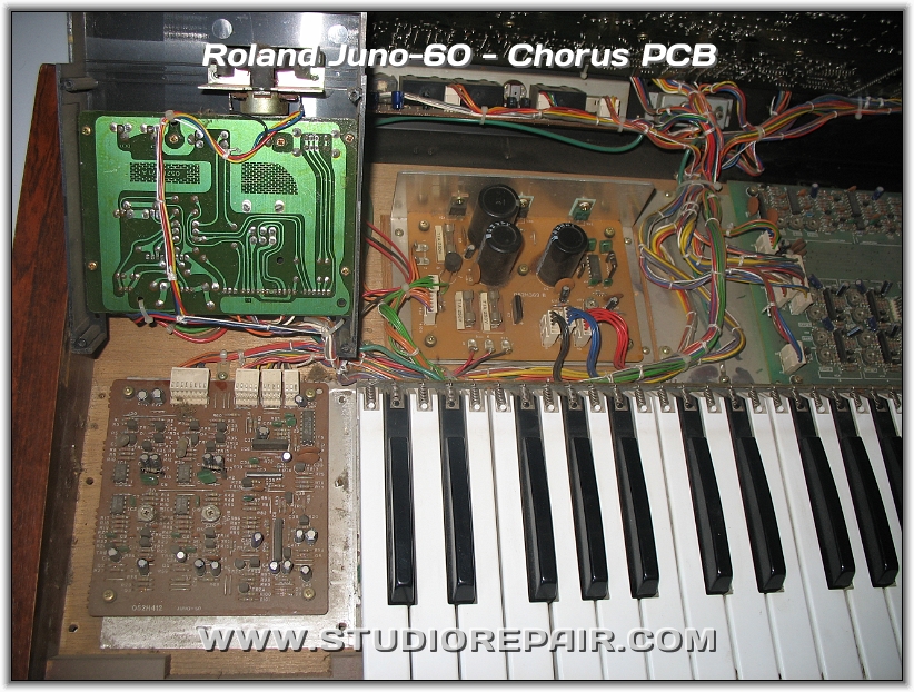
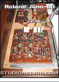
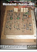
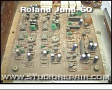
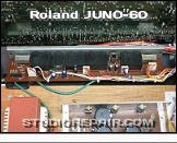
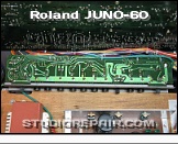
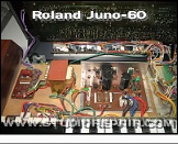
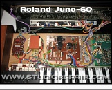
Roland Juno-60
▪ Topic:
Chorus PCB
▪ Abstract:
Left side view with up-lifted bender unit to unsheathe the chorus PCB
▪ Owner:
Equipment courtesy of
Marek Hemmann
▪ Creator:
Image by
Nikolaus Riehm
▪ Website:
www.studiorepair.com
▪ Editor:
Nikolaus Riehm
STUDIO REPAIR
»
Roland
»
JUNO-60
»
Chorus PCB
[Image 46 of 57]
::
Jump To
+ D-50
+ JD-800
+ JD-990
+ JUPITER-4
+ JUPITER-6
+ JUPITER-8
+ JP-8000
+ αJUNO-2
- JUNO-60
+ JUNO-106
+ JX-3P
+ MC-202
+ MKS-20
+ MKS-80 / MPG-80
+ RE-150
+ RE-201
+ RE-301
+ RE-501
+ RS-202
+ SBF-325 - Flanger
+ SH-1
+ SH-2
+ SH-09
+ TB-303
+ TR-606
+ TR-707
+ TR-808
+ TR-909
+ U-220 - Sound Module
+ XP-80 - Workstation
+ XV-5050
Roland Juno-60 • Chorus PCB
Left side view with up-lifted bender unit to unsheathe the chorus PCB
Roland Juno-60 - Chorus PCB - Image by
Nikolaus Riehm
- Equipment courtesy of
Marek Hemmann
©
STUDIO REPAIR NIKOLAUS RIEHM
2006 - 2020